

MOLD & INJECTION MOLDING CASE STUDY
Insert Molding for a Pressure-Tested Plastic Cover with Threaded Metal Inserts
This insert molding project involved a large, thick-wall plastic cover incorporating eight SS316 threaded metal inserts, two hydraulic side actions, post-molding CNC machining and pressure validation. Rather than treating molding, machining and testing as separate operations, SPM developed the part as one controlled manufacturing process from mold design through final inspection.
The component was designed for a demanding fluid application where insert retention, dimensional stability and sealing performance all mattered. Because the part measured approximately Ø325 × 170 mm and weighed about 3.6 kg, the molding process also had to manage a relatively large material mass and long cooling cycle.
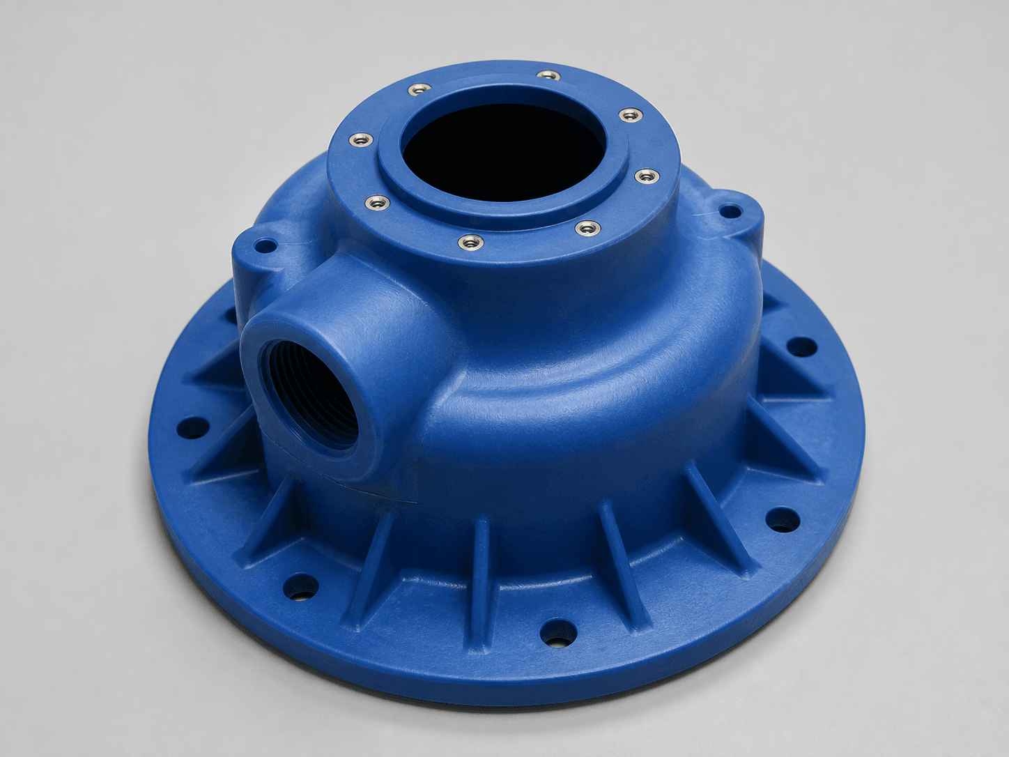
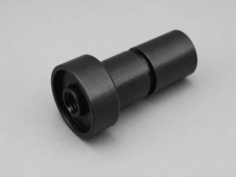
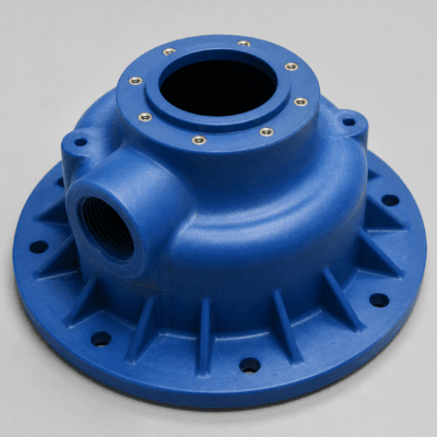
Production component prepared for a fluid-pressure application.
ENGINEERING CHALLENGE
Why This Insert Molding Project Required More Than Standard Injection Molding
Conventional injection molding focuses mainly on producing the plastic geometry. In this project, however, the mold also had to accurately position eight threaded stainless-steel inserts while controlling thick-wall filling, cooling behavior and the movement of two hydraulic sliders.
For reliable insert molding, the inserts must remain correctly located while molten polymer enters the cavity under pressure. Any insert movement, rotation or incomplete encapsulation can affect thread position, mechanical retention and downstream assembly.
What Made the Part Demanding
- Approximately 12 mm average wall thickness and a large molded mass required controlled filling and cooling.
- Eight SS316 threaded nut inserts had to remain securely positioned during molding.
- Two hydraulic side actions were required to create functional side geometry.
- The large part size increased the importance of shrinkage and dimensional control.
- Water-pressure testing made sealing performance a functional requirement rather than a cosmetic quality check.
Tooling Parameters
- Mold envelope: 500 × 600 × 541 mm.
- Injection press: 1,000 ton.
- Production cycle: approximately 7 minutes.
- Two hydraulic side actions integrated into the mold design.
- Eight threaded metal inserts positioned before each molding cycle.
INSERT CONTROL
Controlling Threaded Inserts During Molding
Metal inserts create additional tooling and process requirements because they must be loaded, supported and retained before injection begins. The mold must locate each insert accurately enough to maintain the required relationship between the threaded features and the surrounding plastic geometry.
During insert molding, molten polymer flows around the pre-positioned metal components and mechanically locks them into the finished plastic part. The external shape of the insert and the molded plastic surrounding it both contribute to resistance against pull-out and rotation.
The mold must repeatedly locate each threaded insert in the correct position before the cavity is filled.
The insert must resist displacement caused by resin flow and injection pressure during the molding cycle.
Material flow around the insert must provide sufficient mechanical engagement while avoiding incomplete filling or unwanted flash.
Engineering principle: successful insert molding depends on both part design and tooling design. Insert geometry, locating method, resin flow and surrounding wall structure must be considered together.
MATERIAL & MOLDING
Managing a Large Thick-Wall Engineering Plastic Component
The part was molded from Zytel 70G30HSL NC010, an engineering nylon grade selected for the application requirements. For general background on the Zytel material family, see the Celanese Zytel PA material resource .
Large thick-wall plastic components require careful control because different regions of the molded part may cool at different rates. Uneven cooling can contribute to shrinkage variation, internal stress and dimensional movement after ejection.
For this insert molding application, molding conditions also had to work together with the metal inserts and hydraulic side actions. The objective was not simply to fill the cavity, but to create a stable molded base for the secondary machining and pressure-testing stages that followed.
DELIVERY PROCESS
5-Stage Insert Molding, Machining and Validation Process
The manufacturing route was divided into five connected stages. This approach allowed tooling, molding, post-processing and functional testing to be planned around the final performance requirements rather than handled as unrelated operations.
After molding, the component went through an aging period before secondary machining. This helped separate the main molding stage from the final dimensional operations and reduced the risk of completing precision interfaces before the molded component had sufficiently stabilized.
The post-molding machining sequence included CNC turning, milling, boring, tapping and drilling. These operations created final functional interfaces and threaded locations that required tighter dimensional control than could reasonably be achieved through molding alone.
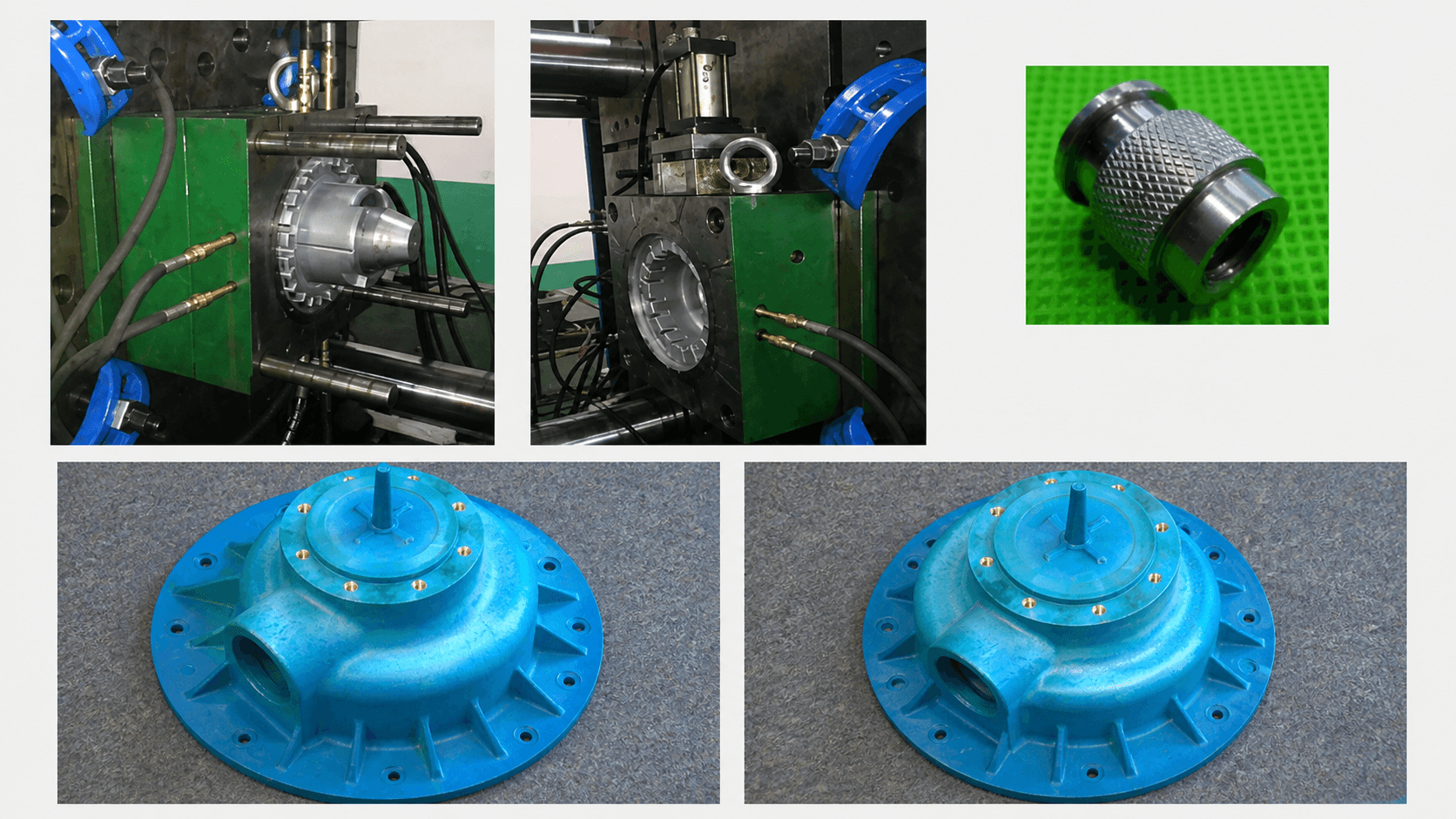
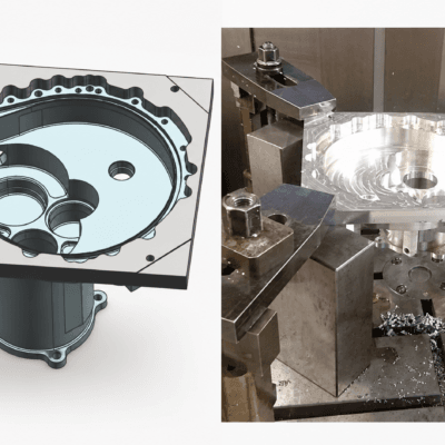
Original project imagery showing injection molding, threaded inserts and the finished insert-molded cover.
Why it matters: for thick-wall insert-molded components, mold design, molding parameters, secondary machining and validation should be engineered as one connected process. Separating these decisions can create avoidable dimensional, fit and sealing risks later in the project.
POST-MOLDING MACHINING
Why CNC Machining Was Used After Insert Molding
Injection molding is highly effective for producing complex plastic geometry, but some functional interfaces still benefit from secondary CNC machining. In this project, the molded component provided the primary form while machining was used to complete selected dimensions and interfaces after the molding stage.
This hybrid approach allowed SPM to use the strengths of both processes. Insert molding integrated the metal threads directly into the plastic component, while CNC machining provided additional control over features such as bores, faces, drilled holes and tapped locations.
The sequence was especially important because machining too early could allow later dimensional movement to affect the final geometry. By performing the main molding operation first and completing critical machining afterward, the process provided a more controlled route to the finished functional component.
PRESSURE VALIDATION
Pressure Testing the Finished Insert-Molded Cover
Because the finished component was intended for a fluid application, visual inspection and dimensional measurement alone were not sufficient. Functional pressure testing was included in the validation plan to confirm that the complete molded and machined assembly could maintain pressure without leakage.
15 Bar Leak Test
The finished cover was subjected to a water-pressure test at 15 bar for 10 minutes. No leakage was reported during the specified test interval.
25+ Bar Destructive Verification
Additional destructive pressure testing exceeded 25 bar, providing a margin check beyond the normal working-pressure validation.
For this type of insert molding project, pressure performance depends on more than the plastic material alone. Molded geometry, insert locations, post-machined interfaces and sealing surfaces all contribute to the performance of the final component.
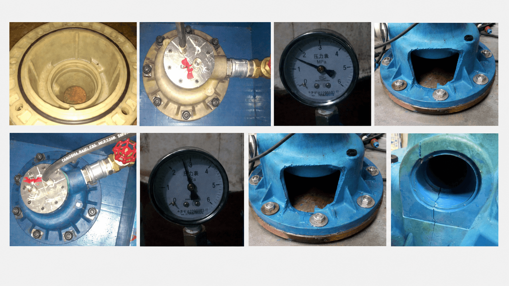
Original project validation imagery showing the pressure-test fixture, gauges and inspected component.
QUALITY CONTROL
Inspection Across Molding, Machining and Final Testing
Quality control for a multi-process component cannot be limited to a single final inspection step. The most effective approach is to verify the characteristics that matter at the stage where they are created.
Check molded geometry, insert position, surface condition and obvious molding defects before secondary operations.
Verify critical dimensions, bores, hole positions, threaded features and machined sealing interfaces.
Confirm functional pressure performance and inspect the finished component before production release.
This staged inspection method helps identify whether a problem originates in tooling, insert molding, secondary machining or final assembly. It also reduces the risk of carrying a defect through multiple manufacturing operations before it is detected.
ENGINEERING TAKEAWAY
A pressure-tested insert-molded component should be engineered as a complete manufacturing system. The tooling, insert location, resin processing, cooling behavior, post-molding machining and functional validation stages all influence the final result. This project demonstrates how combining these operations under one process plan can reduce interface risk and provide clearer control over final part performance.
See more examples in our manufacturing case studies .
FOR YOUR PROJECT
Need Insert Molding with Threaded Inserts, CNC Machining or Pressure Validation?
Send SPM your 2D drawing or 3D model together with material, quantity, insert requirements and functional test conditions. Our engineering team can review mold design, insert positioning, molding feasibility, post-machining and validation requirements before quotation.