

CNC MACHINING CASE STUDY
Gearbox Housing Machining with Controlled Fixturing and Stress Release
This gearbox housing machining project involved a complex, irregular component with relatively thin and distortion-sensitive geometry. Instead of treating fixturing as a simple workholding task, SPM developed the machining route around controlled support, retained machining allowance and a staged roughing, stress-release and finishing sequence.
The main challenge was maintaining dimensional stability as material was progressively removed. For this type of housing, excessive clamping force or an unsuitable machining sequence can allow the workpiece to move during cutting or change shape after it is released from the fixture. The process therefore had to control both machining forces and the way those forces entered the part.

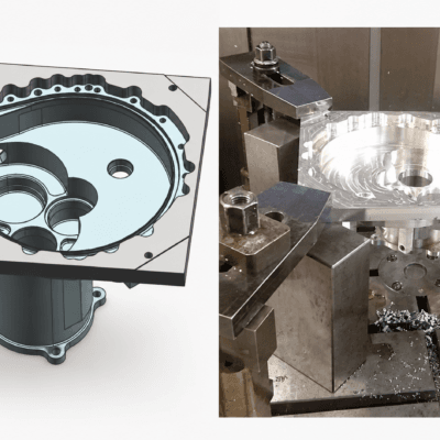
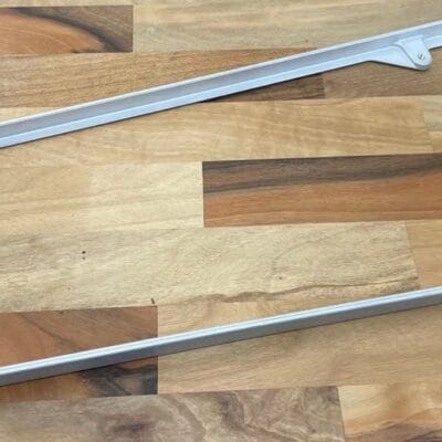
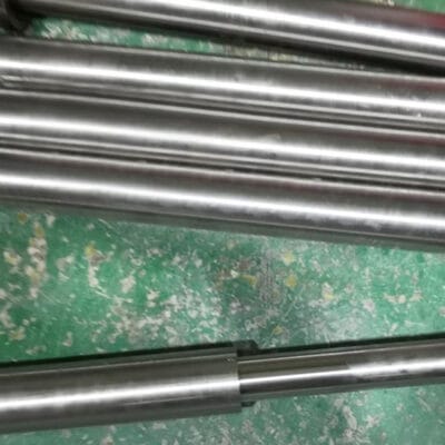
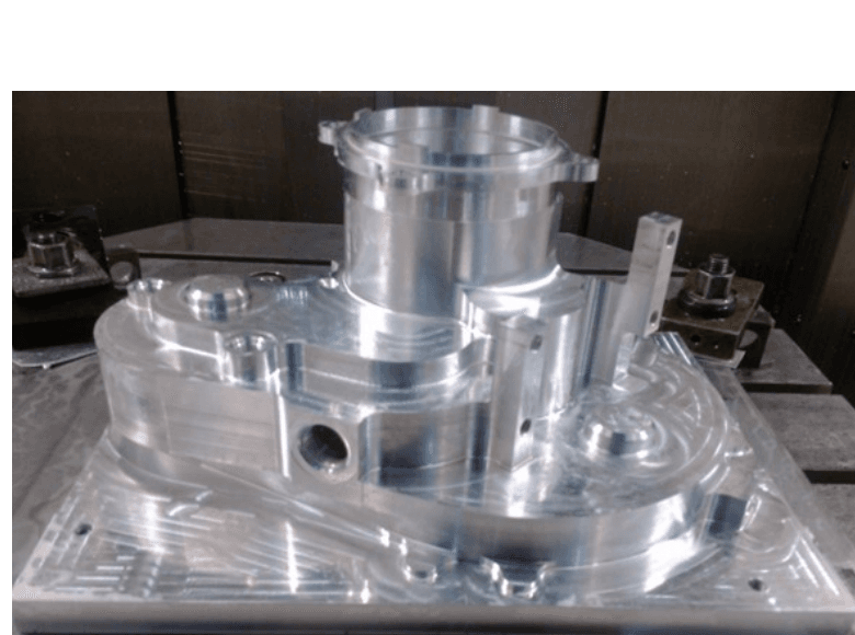
Original project imagery showing the fixture concept and CNC machining setup for the gearbox housing.
MACHINING CHALLENGE
Why Irregular Gearbox Housings Are Difficult to Machine
In gearbox housing machining, the part may contain bores, mounting faces, pockets, bosses and other functional features that must maintain their geometric relationship after machining. At the same time, removing material from an irregular housing reduces its stiffness and can redistribute residual stresses inside the workpiece.
This makes gearbox housing machining more than a question of selecting the correct CNC machine or cutting tool. The workholding strategy, machining allowance, cutting sequence and final release condition all influence whether the finished part remains within tolerance.
Thin or unsupported sections can deflect under cutting and clamping forces, particularly after rough machining removes much of the original material.
Complex housings often provide fewer convenient locations for stable workholding without contacting functional or finished geometry.
A part can appear acceptable while constrained in the fixture and then move after clamping pressure is released or residual stress redistributes.
FIXTURING STRATEGY
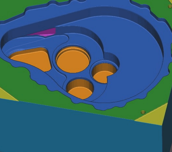
Temporary machining allowance creates a controlled clamping interface and is removed later in the process.
Build the Holding Strategy into the Machining Process
For this gearbox housing machining project, SPM deliberately retained material at selected clamping positions. Rather than forcing the irregular finished geometry to serve as the primary holding surface, this temporary allowance created predictable areas where fixture loads could enter the workpiece.
Allowance was retained at the clamping locations so the fixture could hold the workpiece without applying the main clamping load directly to critical finished surfaces.
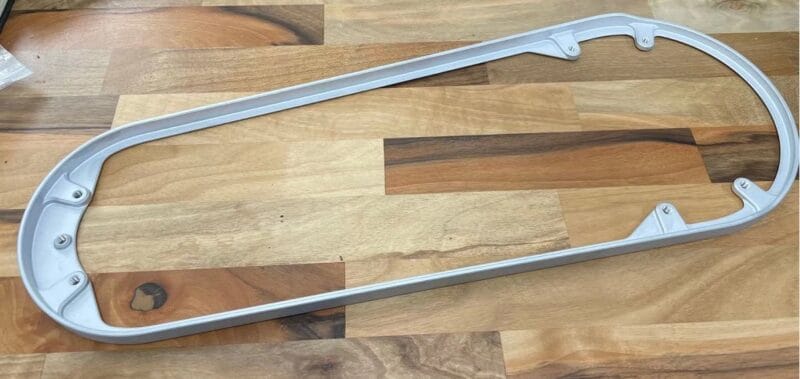
The support plate was made 10 mm thicker at the indicated area to increase local rigidity and provide sufficient support during rough machining.
Clamping pads were set 0.1 mm lower to maintain the required flatness and reduce unwanted interference between the workpiece and fixture.
DISTORTION CONTROL
Controlling Distortion During Gearbox Housing Machining
Increasing clamping force is not necessarily the solution for a flexible housing. If the fixture elastically deforms the workpiece, the machine can produce dimensions that appear correct while the component remains clamped. Once the fixture is released, however, the part may spring back toward its free-state geometry.
For this reason, the fixture was designed to provide support where it was needed while avoiding unnecessary loading of distortion-sensitive regions. The retained machining allowance created a temporary structural and clamping interface, while the reinforced tooling plate helped support the component during material removal.
The strategy also separated rough machining from final finishing. Roughing removes a significant amount of material and changes the stiffness and internal stress balance of the workpiece. Finishing critical geometry immediately after heavy roughing can therefore increase the risk that subsequent movement affects the final dimensions.
Process principle: support the workpiece during heavy material removal, allow stress redistribution before final finishing, and machine critical geometry only after the part has reached a more stable condition.
MACHINING SEQUENCE
Four Controlled Stages Before Final Geometry
The gearbox housing machining sequence was divided into four controlled stages. Each stage had a specific role in maintaining workpiece stability rather than attempting to complete all geometry in one continuous machining operation.
Prepare Fixture
Reserve the planned machining allowance and establish stable, repeatable support on the dedicated tooling plate.
Rough Machine
Remove the majority of material while the housing remains supported and critical functional surfaces are protected from final finishing.
Stress Release
Leave the workpiece free for approximately 24–72 hours so stresses introduced or redistributed during rough machining can partially stabilize.
Finish & Remove
Complete critical geometry and final surfaces, then remove the temporary process ribs, allowance and holding material.
Why the Roughing Layout Matters
The roughing strategy was planned around the fixture and support concept rather than treating workholding as a later shop-floor decision. This allowed the engineering team to consider where machining forces would act while sufficient structural material was still available.
- Support and clamping positions were defined before machining started.
- Temporary material provided additional rigidity during heavy material removal.
- Critical surfaces were reserved for finishing after the stress-release interval.
- Temporary process material was removed only during the final stage.
PROCESS ENGINEERING
Why Machining Sequence Matters as Much as the Fixture
In gearbox housing machining, a well-designed fixture cannot completely compensate for an unsuitable machining sequence. As pockets become deeper and wall sections become thinner, the workpiece stiffness changes continuously. The cutting strategy therefore needs to evolve with the geometry of the part.
In this case, rough machining was performed while additional material was still available to support the housing. Final features were intentionally delayed until after the major material-removal operations and stress-release period. This reduced the chance that critical geometry would be completed while the workpiece was still experiencing its largest structural changes.
The same principle can be applied to other precision housings, frames and irregular machined components. When distortion risk is significant, process planning should connect workholding, material removal, intermediate stabilization and final inspection rather than treating them as independent operations.
For additional background on CNC process planning, setup and inspection, see the Autodesk CNC machining learning resource .
QUALITY CONTROL
Dimensional Stability Is Evaluated After Fixture Release
For distortion-sensitive parts, dimensional verification is most meaningful when the finished component is no longer being artificially constrained by heavy clamping forces. The objective is to produce geometry that remains stable in its functional condition, not merely while it is fixed to the machining table.
The machining and inspection strategy therefore needs to consider important datums, mounting faces, bores and other drawing-defined features after the major machining stresses have been released. This is particularly important for gearbox housing machining, where the relationship between multiple functional features can affect downstream assembly.
Dimensional stability should therefore be considered part of the machining process rather than only a final inspection task. If the workpiece changes shape after unclamping, the cause may be related to fixture pressure, stress redistribution, machining order or insufficient support during material removal.
INSPECTION & VALIDATION
Inspection Strategy for Gearbox Housing Machining
Inspection is especially important when machining a housing with irregular and distortion-sensitive geometry. A dimension that appears correct while the component is heavily constrained may change after the workpiece is removed from the fixture. For this reason, the validation plan for gearbox housing machining should consider not only individual dimensions, but also the condition of the finished part after machining and fixture release.
Critical mounting faces, bearing bores, hole positions and drawing-defined datums need to maintain the required geometric relationship in the component’s functional state. Where appropriate, inspection can combine conventional measuring instruments with CMM measurement to verify dimensional and geometric requirements. The inspection method should be selected according to the drawing tolerances, feature accessibility and the functional importance of each characteristic.
Primary locating and mounting surfaces establish the reference system for evaluating other functional features of the housing.
Bearing bores, hole locations and related features should be verified against the drawing-defined datum structure after final machining.
Final verification helps confirm that critical geometry remains controlled after the component is released from machining fixtures.
For a complex gearbox housing machining project, inspection feedback can also help distinguish between a cutting-process issue and deformation caused by workholding or stress redistribution. If a feature changes after unclamping, simply correcting the tool path may not address the underlying cause. The fixture strategy, support condition and machining sequence may need to be reviewed together.
This closes the manufacturing loop between process planning, machining and quality control. Instead of treating inspection only as a final pass-or-fail operation, measurement results provide engineering feedback for improving subsequent parts. For repeat gearbox housing machining orders, this approach supports a more stable process and helps maintain consistent results across production batches.
ENGINEERING RESULT
For Irregular Housings, Distortion Control Begins with How the Part Is Held
The fixture interface, retained allowance, support stiffness, roughing strategy and finishing sequence need to function as one manufacturing system. This case demonstrates how planned temporary material and dedicated support can create a more controlled gearbox housing machining process for irregular, distortion-sensitive components.
The broader engineering principle is straightforward: workholding should support the component without introducing unnecessary deformation, while the machining sequence should account for changing rigidity as material is removed. For complex housings, fixturing, roughing, stress release, finishing and inspection are most effective when they are planned as one connected process.
See more examples in our CNC machining case studies .
FOR YOUR PROJECT
Need Gearbox Housing Machining for a Complex or Distortion-Sensitive Part?
Send SPM your 2D drawing or 3D model together with material, quantity and critical tolerance requirements. Our engineering team can review machining access, fixture strategy, temporary support, machining sequence and inspection requirements before quotation.