



Tight tolerance CNC machining is not simply a matter of entering a smaller tolerance value on a drawing. As dimensional requirements become more demanding, the entire manufacturing system begins to matter: material stability, machine condition, fixturing, cutting forces, temperature, tool wear, inspection strategy, and even the order in which features are machined.
For designers and buyers, the most useful question is therefore not, “How tight can this dimension be?” It is, “How tight does this feature actually need to be, and can that requirement be manufactured, measured, and repeated consistently?”
A tolerance that protects function can be essential. A tolerance that does not protect function may only increase machining time, inspection effort, scrap risk, and cost.
This guide explains how tight tolerances should be allocated, produced, measured, and balanced against manufacturing economics.
What Is Tight Tolerance CNC Machining?
Every manufactured dimension varies to some degree. A tolerance defines the permitted variation around a nominal size, geometric condition, or functional relationship.
There is no universal numerical point at which ordinary machining suddenly becomes tight tolerance CNC machining. The difficulty of a requirement depends on the feature itself.
A tolerance that is routine on a short, rigid turned diameter may be much more difficult on a deep bore, a thin wall, a long unsupported feature, or two surfaces that must maintain a precise relationship across several machining setups.
Nominal Size Is Only Part of the Requirement
A drawing may control much more than length, width, or diameter. Functional requirements can include flatness, perpendicularity, position, profile, runout, parallelism, or the relationship between multiple features.
That distinction matters because a component can have individually correct dimensions and still fail in assembly. A bore may have the correct diameter, for example, but still create a problem if its axis is incorrectly positioned relative to a mounting surface or mating shaft.
Capability Must Be Evaluated Feature by Feature
Statements such as “this machine can hold a very tight tolerance” are incomplete without part context. Manufacturing capability depends on geometry, material, feature size, tool access, workholding, machine configuration, measurement method, and production quantity.
A realistic tolerance review therefore evaluates the complete feature and its functional relationship rather than focusing on a single tolerance number.
Where Tight Tolerances Actually Matter
The most effective use of tight tolerance CNC machining is selective. Precision should be concentrated on features that directly influence function, assembly, sealing, alignment, motion, or performance.
Fits Between Mating Components
Bearing seats, shafts, bushings, locating pins, sleeves, and precision sliding interfaces often depend on carefully controlled dimensional relationships.
In these applications, tolerance affects clearance, interference, alignment, assembly force, wear, and operating behavior.
The important requirement is often not one dimension in isolation, but the relationship between mating features.
Sealing and Contact Surfaces
Flatness, surface condition, and relative position may become critical where a part must seal against a gasket, O-ring, thermal interface material, or precision mating surface.
Applying equally tight tolerances to unrelated exterior dimensions does not improve sealing performance. It only adds manufacturing burden.
Locating and Alignment Features
Dowel holes, bearing bores, optical mounts, alignment pins, and assembly datums may require accurate positional relationships.
In these cases, GD&T can often describe function more effectively than applying very narrow plus/minus tolerances to several coordinate dimensions.
Rotating and Coaxial Features
Shafts, bearing interfaces, rotary assemblies, and certain optical or fluid components may depend on controlled runout, coaxiality, or geometric alignment.
Producing these features in a common setup can often reduce the number of error sources compared with machining them independently and trying to recover alignment later.
Features That Do Not Need Tight Control
Many non-mating exterior surfaces, clearance pockets, cosmetic reliefs, and non-functional dimensions do not benefit from precision beyond what the product requires.
Over-tolerancing these areas can increase cost without creating measurable functional value.
Material Selection and Dimensional Stability
Material behavior is a major consideration in tight tolerance CNC machining because different materials respond differently to heat, cutting forces, clamping, residual stress, and material removal.
Aluminum Alloys
Aluminum is widely used because it machines efficiently and offers a useful combination of low density, corrosion resistance, and thermal conductivity.
For precision work, however, its relatively low stiffness means thin sections can deflect under cutting or clamping forces. Aluminum also responds noticeably to temperature changes, which becomes increasingly important when the allowable dimensional variation is small.
Large pockets, thin walls, and asymmetric material removal can also release residual stress and cause a component to move after rough machining.
Stainless Steel
Stainless steels can provide excellent strength and corrosion resistance, but many grades generate more cutting heat and cutting force than common aluminum alloys.
Tool wear, heat concentration, work hardening, and chip control may therefore become more important in a tight-tolerance process.
The correct machining strategy depends heavily on the particular stainless grade rather than the material family alone.
Titanium and Other Difficult Alloys
Titanium alloys can combine high strength with relatively low thermal conductivity, causing heat to remain concentrated near the cutting zone.
Tool condition, cutting parameters, coolant strategy, and machine rigidity therefore become especially important when dimensional stability must be maintained over a production run.
Engineering Plastics
Precision machining of engineering plastics introduces a different set of challenges. Some plastics are more sensitive to heat, moisture, internal stress, clamping pressure, or post-machining dimensional relaxation.
A dimension that measures correctly immediately after cutting may change as the component reaches thermal or moisture equilibrium.
Material conditioning and measurement timing can therefore become part of the manufacturing plan.
Material Selection Should Reflect Functional Priorities
The easiest material to machine is not always the best material for the product. Material selection should balance structural requirements, environmental exposure, thermal behavior, surface treatment, availability, and manufacturing stability.
For tight tolerance CNC machining, dimensional stability should be treated as one of those design inputs rather than an issue left entirely to the machine shop.
Thermal Effects in Precision Machining
Thermal control is a central part of tight tolerance CNC machining because both the workpiece and the manufacturing system change dimension as temperature changes.
Parts Change Size With Temperature
Engineering materials expand and contract as temperature changes. ISO dimensional metrology uses 20°C as the standard reference temperature for geometrical and dimensional properties.
This does not mean that every component must physically remain at exactly 20°C during production. It means that temperature differences must be understood whenever thermal expansion becomes significant relative to the allowable tolerance.
Measuring a warm part immediately after heavy cutting can produce a different result from measuring the same part after it reaches thermal equilibrium.
The Machine Also Changes With Temperature
The workpiece is only one part of the thermal system. Spindles, ball screws, machine structures, coolant, fixtures, and the surrounding environment can also change temperature during production.
A machine that has just been started may not behave exactly the same as the same machine after extended operation.
Coolant and Process Stability
Coolant can influence cutting temperature, chip evacuation, tool life, and process consistency. In demanding applications, coolant temperature stability may also contribute to overall dimensional stability.
The objective is not to eliminate heat entirely, which is impossible. The objective is to keep the thermal condition predictable enough that the process remains repeatable.
Measurement Temperature Matters Too
A precision measurement is meaningful only in the context of the part’s temperature and the measurement environment.
If the machining area, inspection area, customer laboratory, and final operating environment differ substantially, the relationship between those conditions should be understood when requirements become particularly demanding.
Machine, Tooling, and Fixturing Stability
Successful tight tolerance CNC machining depends on the stability of the complete cutting system, including the machine, tool, fixture, workpiece, and process conditions.
Machine Rigidity and Condition
Machine structure, spindle condition, axis accuracy, backlash control, positioning repeatability, and thermal behavior all contribute to the final result.
A high-quality CNC machine provides an important foundation, but machine specification alone does not guarantee the finished feature.
Tool Deflection
A cutting tool bends under load. Longer projection, smaller diameter, heavier cutting forces, and reduced rigidity generally increase deflection.
This becomes especially important for deep cavities, small internal features, tall walls, and finishing operations where the remaining dimensional allowance is small.
Reducing unnecessary tool reach and improving feature access can sometimes improve accuracy more effectively than simply specifying a tighter tolerance.
Tool Wear
Tool geometry changes gradually during machining. That change can alter size, surface condition, cutting force, chip formation, and thermal behavior.
For a very small batch, one tool may remain sufficiently stable throughout production. For longer runs, however, tool wear becomes part of the dimensional control problem.
Possible responses include scheduled tool changes, offset adjustment, in-process measurement, or monitoring of critical dimensions over time.
Fixture Stability
A fixture must locate the workpiece repeatably without distorting it.
Excessive clamping force can deform thin or flexible parts. Insufficient clamping can allow movement under cutting load. Poor contact between locating surfaces can introduce variation each time a new part is loaded.
Good workholding therefore balances rigidity with controlled restraint.
Same-Setup Machining
When two critical features must maintain a precise relationship, producing them in the same setup often removes an entire layer of repositioning uncertainty.
Multi-axis machining can sometimes make this possible by reaching additional surfaces without manually removing and re-fixturing the workpiece.
Geometry That Makes Tight Tolerances Difficult
In tight tolerance CNC machining, geometry often determines whether a dimensional requirement can be produced economically and repeated consistently.
Thin Walls
Thin sections can move during cutting, clamping, unclamping, and inspection.
A wall may deflect away from the tool while material is being removed and then spring back after the cutting force disappears. A part may also measure differently while clamped than after it is removed from the fixture.
Possible strategies include preserving temporary support material until late in the machining sequence, balancing operations, reducing finishing forces, and avoiding unnecessarily thin geometry near critical surfaces.
Deep Bores and Cavities
Deep features increase tool reach and reduce accessibility for both cutting and inspection.
A bore may be straightforward to measure near its entrance but more difficult deeper inside. A deep pocket may require long tooling that is more sensitive to vibration and deflection.
Design changes that improve access can sometimes reduce manufacturing risk substantially.
Long and Slender Components
Long shafts and slender turned components can deflect under cutting forces.
Workpiece support, cutting pressure, tool geometry, process sequence, and rotational behavior all influence the final geometry.
Large Flat Parts
Large plates and frames may distort when significant material is removed from one side or when clamping forces are distributed unevenly.
Flatness problems may only become visible after the part is removed from the fixture.
Features Across Multiple Setups
If two related features cannot be machined in the same setup, their final relationship begins to depend on fixture location, datum transfer, probing, repositioning accuracy, and accumulated error.
Whenever practical, critical related features should be planned around a common datum structure and a sequence that minimizes unnecessary reorientation.
Process Planning for Tight Tolerance Parts
A strong tight tolerance CNC machining process is usually designed as a controlled sequence rather than a single cutting operation.
Roughing
Rough machining removes the majority of excess material efficiently. At this stage, the priority is usually material removal rather than final dimensional accuracy.
Critical features are commonly left with sufficient remaining stock for later semi-finishing or finishing operations.
Allowing the Part to Stabilize
Heavy material removal can change the internal stress state of a component. Depending on the geometry and material, the part may move after roughing.
For demanding components, separating roughing and finishing gives the part an opportunity to stabilize before final dimensions are established.
Semi-Finishing
A semi-finishing step can bring geometry closer to final size while leaving a small, controlled amount of material for the final cut.
This can make the finishing operation more predictable because the final tool engagement is more consistent across the surface.
Finish Machining
Finish passes should be planned around stable cutting conditions, suitable tooling, controlled tool engagement, and sufficient rigidity.
The exact stock allowance and cutting strategy depend on the material, feature, and process, so universal values should be avoided.
Machining Critical Features Late
Where practical, some critical surfaces can be finished after the most distortion-producing operations are complete.
This reduces the chance that later material removal will alter a feature that has already been brought to final size.
Controlling Datum Transfers
If a part must be re-fixtured, the next setup should reference surfaces that were deliberately established for that purpose.
Randomly transferring dimensions through secondary surfaces can increase accumulated variation.
In-Process Probing
Machine probing can help confirm workpiece location, fixture position, or selected dimensional conditions before the part leaves the machine.
Probing does not replace final inspection, but it can reduce the delay between process drift and corrective action.
Offset Compensation
When a stable trend is observed, tool offsets can sometimes be adjusted to compensate for gradual dimensional drift caused by tool wear or other predictable process changes.
This approach works best when the underlying process is already stable. Compensation should not be used to hide uncontrolled variation.
GD&T, Datums, and Tolerance Stack-Up
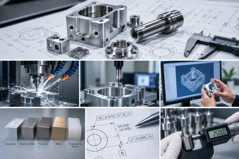
Tight tolerance CNC machining becomes easier to manufacture and inspect when a drawing clearly describes functional intent.
ASME Y14.5 establishes practices for stating and interpreting GD&T, while ISO 1101 provides standardized rules for geometrical tolerancing.
Start With Functional Datums
A datum reference frame should reflect how a component functions, assembles, or is inspected.
Stable, accessible functional surfaces make it easier to align machining, measurement, and assembly around the same reference system.
Position Instead of Over-Toleranced Coordinates
Hole patterns provide a common example. Very narrow bilateral X and Y tolerances may not describe the true functional requirement as effectively as a positional tolerance relative to appropriate datums.
Correct geometric controls can provide manufacturing freedom while still protecting assembly function.
Flatness and Orientation
Flatness controls a surface independently, while perpendicularity, parallelism, and other orientation controls describe relationships to a datum.
Understanding the difference helps avoid drawings that accidentally impose more control than the product actually requires.
Tolerance Stack-Up
Assemblies contain multiple dimensions whose variation contributes to a final functional condition.
Tightening one component dimension without understanding the complete stack may increase cost without solving the real assembly problem.
Before reducing individual tolerance bands, determine how each dimension contributes to the final fit, clearance, alignment, or preload condition.
Inspection and Measurement Strategy
Inspection is an essential part of tight tolerance CNC machining because a tolerance is only useful when it can be verified with a sufficiently capable measurement method.
Match the Measurement Method to the Feature
| Feature | Possible Inspection Method | Main Consideration |
|---|---|---|
| Outside diameter | Micrometer | Access and measurement force |
| Bore diameter | Bore gauge / internal measurement | Depth, taper, and roundness |
| Hole position | CMM | Datum alignment |
| Flatness | CMM / surface measurement | Support and measurement strategy |
| Thread | Thread gauge / dedicated measurement | Functional acceptance |
| Complex profile | CMM / optical system | Accessibility and uncertainty |
CMM Inspection
Coordinate measuring machines are especially useful when a feature must be evaluated relative to a datum system or when several geometric relationships must be measured in a common coordinate frame.
CMM inspection can be powerful, but the probing strategy, fixture method, datum alignment, and environmental condition still influence the result.
Micrometers, Bore Gauges, and Functional Gauging
For simple sizes, conventional measuring tools can be faster and more economical than full CMM inspection.
A micrometer may be ideal for an accessible outside diameter, while a bore gauge may provide useful information about an internal feature.
Functional gauges can also be valuable when the key question is whether a feature performs correctly in assembly rather than what its exact numerical size happens to be.
Measurement Uncertainty
No measurement system is perfectly exact.
Instrument capability, calibration, fixture method, operator technique, probing strategy, temperature, cleanliness, and surface condition can all contribute to measurement uncertainty.
As the tolerance becomes smaller, that uncertainty becomes a larger percentage of the acceptance range.
Gauge Repeatability and Reproducibility
For recurring production, it may be useful to understand whether different operators or repeated measurements produce sufficiently consistent results.
If the inspection method itself varies too much, it becomes difficult to separate manufacturing variation from measurement variation.
First Article Inspection
The first article often receives broader dimensional verification because it confirms the setup, program, tooling, process sequence, and drawing interpretation.
In-Process Inspection
Critical dimensions can sometimes be checked during production so that gradual drift is detected before an entire batch is completed.
Final Inspection
Final inspection confirms that the finished product satisfies the agreed drawing and quality requirements after all applicable machining and secondary operations are complete.
Common Tight Tolerance Failure Modes
Common failures in tight tolerance CNC machining often reveal whether the underlying problem comes from process drift, thermal effects, material movement, tooling, workholding, or measurement.
Dimension Drifts During the Batch
A feature may start near nominal size and gradually move toward one side of the tolerance band.
Possible contributors include tool wear, heat accumulation, machine thermal drift, fixture contamination, or changing cutting conditions.
The Part Passes While Warm but Fails After Cooling
This is a classic thermal problem. The part was measured before reaching the temperature condition used for acceptance.
The solution is not automatically to change the CNC program. The measurement timing and thermal state must first be understood.
A Thin Wall Moves After Unclamping
The feature may be held in position by the fixture during inspection or machining, then relax after clamping force is removed.
Possible responses include changing the workholding strategy, machining sequence, wall geometry, or finishing method.
Bore Size Changes as Tooling Wears
Tool wear can gradually affect cutting geometry and cutting force.
If the change is predictable, monitoring and controlled offset adjustment may help. If the process is unstable, the root cause should be corrected rather than continuously compensated.
Hole Sizes Pass but Position Fails
This usually indicates that the individual features are acceptable but their relationship to the datum system or to each other is not.
It illustrates why size tolerances alone cannot always describe assembly function.
Supplier and Customer Measurements Disagree
Differences can result from datum interpretation, measurement method, temperature, equipment, fixture strategy, surface condition, or the way the geometric requirement is evaluated.
For demanding features, the drawing and quality agreement should make the acceptance method sufficiently clear before production begins.
Why Tight Tolerances Increase Cost
Tighter tolerances generally raise cost because they reduce manufacturing freedom and increase the level of process control required in tight tolerance CNC machining.
More Controlled Machining
Critical finishing passes may require conservative cutting conditions, stable tooling, additional spring passes, controlled tool engagement, or specialized cutting tools.
More Complex Workholding
Flexible or difficult geometry may require dedicated fixtures to establish reliable datums and support the part without distortion.
More Inspection
The closer a feature operates to process capability, the more important it becomes to verify the feature during production.
Measurement equipment, operator time, documentation, and inspection cycles all contribute to cost.
Longer Process Development
A demanding component may require more process planning, test cuts, fixture development, tool selection, or inspection planning before stable production is achieved.
Higher Scrap and Rework Risk
A wide process window can absorb normal manufacturing variation. A narrow tolerance leaves less room for temperature changes, tool wear, setup variation, material movement, or measurement uncertainty.
This does not mean precision should be avoided. It means precision should be purchased where it creates functional value.
Choosing the Right Precision Manufacturing Process
The most economical tight tolerance CNC machining strategy does not always rely on one manufacturing process from start to finish.
CNC Milling
Milling is well suited to prismatic parts, pockets, surfaces, hole patterns, housings, and complex multi-axis geometry.
Multi-axis machining can reduce setup transfers and help maintain relationships between features located on different faces.
CNC Turning
Turning is naturally suited to rotational geometry such as shafts, sleeves, bushings, and cylindrical interfaces.
Critical diameters and coaxial features can often be produced efficiently when they are machined in a common setup.
Swiss-Type Machining
Swiss-type machines can be advantageous for small, slender, feature-rich turned components because the workpiece is supported close to the cutting zone.
Whether Swiss machining is appropriate depends on geometry, bar stock, tooling, volume, and the complete process rather than tolerance alone.
Grinding
Grinding may be used when a surface or diameter requires a level of dimensional control, geometry, or finish that is more economical to achieve after conventional machining.
In some cases, machining can establish the basic geometry while grinding provides the final precision surface.
EDM
Electrical discharge machining can be useful for certain hard materials, narrow internal features, sharp internal details, or geometry that is difficult to reach with conventional cutting tools.
It is not automatically the best choice for every tight-tolerance feature, but it can complement CNC machining when geometry makes mechanical cutting inefficient.
Do Not Force One Process to Do Everything
The most economical manufacturing plan sometimes combines processes.
A component may be CNC machined to establish most geometry, then use grinding, EDM, honing, lapping, or another finishing process only where the functional requirement justifies it.
DFM Strategies for Tight Tolerance Parts
Design for manufacturability can improve the stability and economics of tight tolerance CNC machining without necessarily changing the nominal tolerance.
1. Identify Critical Characteristics
Clearly identify the dimensions and geometric controls that directly affect fit, function, sealing, motion, or alignment.
Do not force the manufacturer to guess which dimensions matter most.
2. Use a Clear Datum Structure
Choose datums that relate naturally to component function and can also be accessed during machining and inspection.
3. Avoid Unnecessary Precision
If a clearance pocket, cosmetic surface, or non-mating feature does not affect performance, allow a practical manufacturing tolerance.
4. Design for Tool Access
Shorter and more rigid tooling generally creates a more stable cutting condition than long-reach tooling.
Open geometry, practical corner radii, and accessible features can improve both accuracy and productivity.
5. Reduce Setup Transfers
Where critical features share a geometric relationship, consider whether they can be machined in one setup or referenced from a common functional datum.
6. Consider Material Movement
Large pockets, thin sections, asymmetric stock removal, and slender geometry should be reviewed for possible distortion before critical tolerances are finalized.
7. Separate Functional and Cosmetic Requirements
A cosmetic requirement and a dimensional requirement are not the same thing.
Keeping them clearly separated helps prevent unnecessary precision from being applied to appearance-related surfaces.
8. Define the Inspection Requirement
If a feature is important enough to receive a very demanding tolerance, consider whether the drawing or quality documentation should also clarify the required inspection or acceptance method.
Tight Tolerance CNC Machining Checklist
Before releasing a precision component for quotation or production, review the following questions:
- Which dimensions directly control part function or assembly?
- Are tight tolerances concentrated on those critical features?
- Is the datum structure based on stable and accessible functional surfaces?
- Can critical related features be machined from a common setup or reference?
- Could thin walls, long reaches, or heavy material removal cause distortion?
- Has temperature sensitivity been considered for demanding dimensions?
- Can every critical requirement be measured with an appropriate inspection method?
- Are geometric relationships better expressed with GD&T than coordinate dimensions?
- Has the full assembly tolerance stack been reviewed before individual tolerances are tightened?
- Are non-functional dimensions allowed enough manufacturing freedom?
Preparing a Quote-Ready Precision Drawing Package
A complete RFQ helps a machining supplier evaluate process capability, inspection requirements, and cost before production begins.
For tight tolerance CNC machining, a useful package normally includes:
- a current 3D model, preferably in a neutral CAD format such as STEP,
- a controlled 2D drawing with dimensions and GD&T requirements,
- material and temper or material condition,
- surface finish and coating requirements,
- critical characteristics clearly identified where appropriate,
- inspection or documentation requirements,
- initial order quantity and expected production volume, and
- mating-part or assembly information needed to understand functional tolerances.
The earlier these requirements are reviewed, the easier it becomes to distinguish genuinely necessary precision from tolerances that can be relaxed without affecting product performance.
A good manufacturing review should not focus only on whether a dimension can theoretically be achieved. It should consider whether that requirement can be produced repeatedly, inspected reliably, and maintained economically over the intended production quantity.
Have a Tight Tolerance CNC Machining Project?
Send us your drawing, 3D model, material, quantity, and critical tolerance requirements. We can review manufacturability, machining strategy, inspection considerations, and potential cost drivers before quotation.