



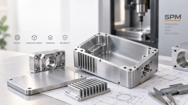

The Functional Roles of a Machined Aluminum Housing
Machined aluminum housings rarely fail because a single dimension is wrong. They fail because the part is being asked to do five jobs at once, and those jobs pull the design in different directions.
Five Functions, One Part
Every machined enclosure carries structural, thermal, protective, locational, and cosmetic responsibilities simultaneously. It supports internal components and resists installation or vibration loads. It conducts heat away from whatever generates it. It keeps out dust, moisture, and electrical interference.
It also holds optical, electrical, or mechanical elements at a precise relative position. And on visible surfaces, it has to look finished.
How Function Cascades into Constraint
Each of these roles converts into a geometric, material, or precision requirement, and the requirements routinely conflict. A wall thin enough to conduct heat efficiently may not be stiff enough to resist vibration. A tolerance tight enough to guarantee a sealed joint may be tighter than the budget can absorb elsewhere on the part.
Design for manufacturability, in this context, is not a checklist of isolated rules — it is a chain of decisions where each choice narrows the options available downstream. That cascade, from function to geometry to machining constraint to cost, is the thread running through the rest of this guide.
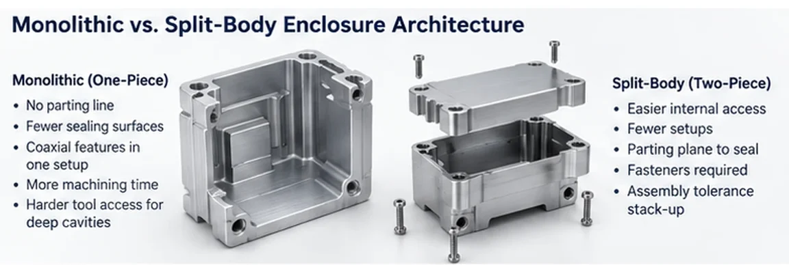
Monolithic vs. Split-Body: The Architecture That Sets the Cost Floor
For machined aluminum housings, one early decision sets the ceiling — or floor — for almost every cost driver that follows: should the housing be a single monolithic block, or an assembly of two or more machined halves?
Monolithic Housing: Fewer Seams, More Machining
A one-piece housing eliminates assembly tolerance stack-up and reduces the number of sealing surfaces to manage. Coaxial features stay coaxial because they are cut in the same setup, and there is no parting line to seal or align.
The trade-off shows up on the machining side: deep internal cavities become harder to reach, the part typically needs more setups to access every face, and material removal — along with scrap — climbs as stock is machined away to leave a hollow shell. This approach tends to suit compact, high-precision enclosures, or designs where a sealed rating like IP66/IP67 is a hard requirement.
Split-Body: Easier Machining, More Interfaces
Splitting the housing into two or more bodies opens up internal cavities for shorter, more rigid tooling and generally reduces the setups needed per part. The cost of that convenience is a parting plane: a new sealing interface, fasteners to hold it closed, and an assembly tolerance chain that a monolithic design avoids.
Split-body construction tends to make sense for larger enclosures, designs with dense internal geometry, or products that need field serviceability.
The Architecture Decision Drives Cost
Setup count, material utilization, and the number of sealing surfaces to manage all trace back to this one decision. Before committing, it is worth ranking the priorities explicitly: how much does internal accessibility matter, how critical is the sealing requirement, and how tight does the precision need to be?
Whichever way that trade-off resolves, it sets the stage for the next decision — the material the housing will be cut from.
Alloy Selection and Stock Form: Locking Material Before Machining
For machined aluminum housings, material selection affects machinability, anodizing response, thermal behavior, achievable strength, and total manufacturing cost. The stock form also determines how much of that material becomes the finished component and how much ends up as chips.
Comparing the Workhorse Alloys
Stock Form: Plate, Bar, Extrusion, or Casting
Flat or shallow housings are usually cut from plate, where material utilization is the main lever for cost. Cylindrical bodies typically start from bar stock, often on turn-mill equipment.
Extrusion offers a near-net starting cross-section that can reduce machining time significantly for constant-profile geometry, but it comes with tooling cost and a minimum order quantity that only makes sense at volume.
For complex internal cavities combined with a few precision interfaces, a cast blank finished with CNC operations on the critical features can be a workable hybrid — accepting looser tolerances on the bulk of the part in exchange for lower cost on non-critical volume, while machining only the surfaces that need to be accurate.
Cavities, Walls, Ribs, and Bosses: Designing Geometry Around the Cutter
For machined aluminum housings, this is where geometry meets the physical limits of the cutting tool, and it is usually where a design either machines cleanly or comes back from the shop floor with chatter marks, missed tolerances, or a request for rework.
Deep Cavities and the Cutter Reach Limit
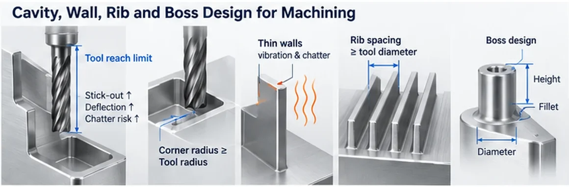
Every deep pocket is bounded by how far a cutting tool can extend before it loses rigidity. As tool stick-out increases relative to its diameter, deflection under cutting load grows, and with it the risk of chatter and degraded surface finish.
There is no single ratio that applies across every combination of tool, material, and machine — what holds for a rigid four-flute end mill in a stiff spindle does not hold for a long, slender tool reaching into a narrow pocket.
In practice, cavity depth should be treated as a design variable that trades off against wall thickness, corner radius, and the number of roughing passes required, rather than a figure fixed early and left unquestioned. Common mitigations include opening up corner radii, roughing in multiple depth passes, switching to ball-nose or plunge-style tooling for the deepest sections, or reconsidering the split-body option discussed earlier.
Thin Walls and the Vibration Problem
Thin sections deflect under cutting force, and that deflection is the root of chatter: a self-exciting vibration that leaves a poor surface finish and, in extreme cases, a wall that ends up thinner — or more out-of-flat — than intended.
There is no universal minimum wall thickness that applies to every housing; the achievable minimum depends on the height of the feature above its supporting material, the alloy, and the order in which features are machined relative to each other. A wall that is well supported through most of the cutting sequence and only becomes thin in the final pass behaves very differently from one that is thin from the start.
Design responses include leaving temporary support stock to be removed last, machining symmetric features in a balanced sequence, and reducing depth of cut on the finishing pass.
Ribs and Gussets: Stiffening Without Solid Stock
Ribs add stiffness with a fraction of the material a solid wall would need, which helps counter the thin-wall deflection problem above. But a rib is still a feature the cutter has to reach: the gap between adjacent ribs needs to stay wide enough for a standard tool.
The fillet at the base of each rib should not be tighter than the radius of the tool used to cut it — otherwise the tool simply cannot produce that corner and it gets left as a stress-concentrating sharp corner instead. The precise multiplier some references quote for this radius varies by source and by tool geometry; the safer working principle is simply that the internal radius should not be smaller than the cutting tool’s own radius, with margin for clearance.
Bosses for Fasteners and Locating Pins
Bosses provide local extra material where a thread, a locating pin, or a standoff needs more depth than the surrounding wall can offer. The boss diameter-to-height ratio, the fillet at its base, and tool accessibility around it all matter.
Where a boss rises from a thin wall, a generous transition fillet is what prevents both stress concentration in service and distortion during machining, since a sharp transition is exactly where cutting-induced stress tends to concentrate.
Datums and Mating Interfaces: Giving the Part a Stable Frame of Reference
Machined aluminum housings need a consistent frame of reference for two separate purposes: holding the part accurately during machining and locating it correctly during assembly. Datums are how that frame of reference gets defined and communicated on the drawing.
Choosing the Primary Datum
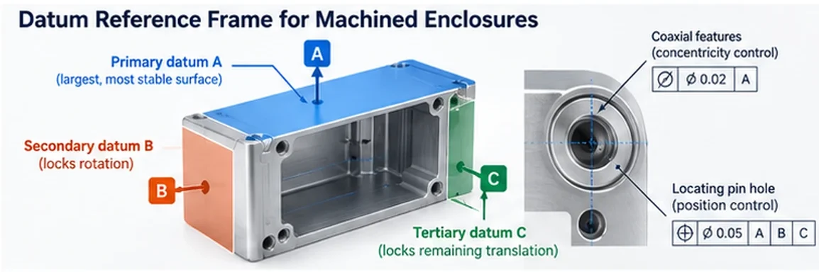
The primary datum should be the largest, most stable functional surface available — not simply the most convenient one to draw. When that same surface also serves as the fixturing face during machining, the part is measured and held against the same reference it was cut against, which removes one source of setup-to-setup error before it can accumulate.
Secondary and Tertiary Datums for Orientation
Secondary and tertiary datums lock the remaining degrees of freedom — rotation and the two in-plane translations the primary datum does not constrain. These choices should not be made in isolation from how the part will eventually be inspected.
A datum surface that a CMM probe cannot physically reach or clamp against is a datum that looks correct on the drawing but is difficult to verify in practice.
Coaxial and Concentric Interfaces
Bearing bores, lens seats, and other rotating or optical interfaces that must share a common axis benefit from being machined in a single setup on a monolithic body, since coaxiality achieved in one operation does not depend on how well two separately machined halves line up afterward.
Where the architecture is split-body instead, that same coaxiality has to be recovered through the joint, which is one more argument for weighing the monolithic-versus-split decision carefully before cutting begins.
The Thermal Interface: Designing a Low-Resistance Heat Path
For machined aluminum housings that carry heat-generating components, the enclosure is one link in a chain that starts at the component junction and ends at the surrounding air — and the housing’s own material is often not where most of the resistance in that chain builds up.
The Heat Path and Where Resistance Builds
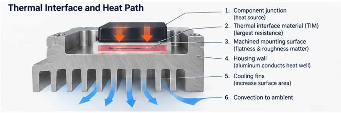
Heat travels from the component package through a thermal interface material, across the machined mounting face, through the housing wall, and finally off a heat-dissipating surface into the environment.
The largest single resistance in that chain is frequently the mechanical interface between the component and the housing — not the aluminum itself, which conducts heat well by comparison.
The Machined Mounting Surface Matters
Flatness and surface roughness at the mounting face directly affect how well a thermal interface material can make contact and conduct heat.
Where fins are machined directly into the housing rather than attached separately, the same cutter constraints from the cavity discussion apply: fin spacing is set by the diameter of the tool that has to cut between them, and fin depth is limited by how far that tool can reach without losing rigidity — this is the same cutter-reach problem discussed earlier, applied to a different feature.
TIM Selection and Clearance Design
A thermal interface material only reaches its rated performance once it has been compressed to a specific thickness, which means the housing has to leave a controlled, tolerance-sensitive gap for that compression to happen.
The correct clearance is not a fixed number that applies across materials — it depends on the specific TIM datasheet in use, and it is worth confirming against that datasheet rather than assuming a figure that worked on a previous project will carry over.
Threads, Fastener Access, and Sealing: Assembly Reality Meets Machining
For machined aluminum housings, the design is only complete once the enclosure can be closed, fastened, and reliably sealed. Threads, tool access, and sealing features are grouped together here because they share the same underlying question: what does assembly actually require, and how does that requirement constrain the machining?
Threaded Holes and Bosses for Fasteners
Metric ISO threads and UNC/UNF threads follow well-established tolerance classes under ISO 965-1 and ASME B1.13M respectively, and choosing between them is usually driven by the fastener standard already in use elsewhere on the product rather than by the housing alone.
For blind holes, the tap drill depth and thread length need enough margin below the last full thread to avoid a weak or incomplete engagement — the safe approach is to size for adequate engagement length rather than defaulting to a fixed multiple of diameter without checking the actual joint requirement.
In hard alloys or deep holes, thread milling is often a more reliable alternative to tapping, since it puts less torque-related stress on the tool and the part.
Fastener Tool Access
A thread is only useful if a driver can actually reach it and rotate. Fasteners recessed in deep cavities, tucked close to an adjacent wall, or oriented so a socket cannot swing through its full arc are a recurring source of assembly problems that show up late, often after the part has already been machined.
Leaving deliberate clearance for both entry and rotation of the intended tool avoids redesign after the fact.
O-Ring Grooves and Sealing Features
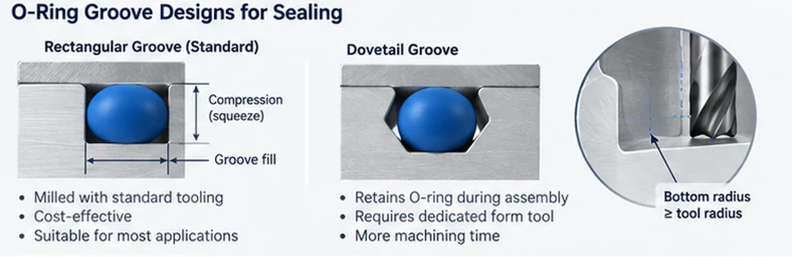
Two groove geometries dominate practical designs: a rectangular groove, which is the most economical to mill with standard tooling, and a dovetail groove, which retains the O-ring against gravity or vibration but requires a dedicated form tool and more machining time.
As with ribs, the radius at the bottom of the groove has to match the tool that cuts it. Compression and fill targets for the seal follow published references such as Parker’s O-Ring Handbook (ORD 5700) and ISO 3601-1, both of which express these targets as ranges rather than single fixed values.
The correct target depends on the specific O-ring cross-section and groove design in use. Surface finish on the groove floor should be set according to the sealing manufacturer’s recommendation rather than an assumed default roughness value.
IP Rating and Sealing Realism
An IP rating like IP65, IP66, or IP67 defines the sealing target, but it does not by itself dictate a specific compression percentage — that mapping depends on the seal design and material chosen.
What the architecture decision from earlier in this guide does dictate is how many sealing surfaces exist to manage in the first place: a split-body design introduces at least one parting-line seal that a monolithic housing simply does not have.
Anodizing and Finishing Allowance: Where Final Dimensions Change Last
For machined aluminum housings, anodizing should be treated as both a finishing process and a dimensional consideration. It happens after machining, which means it is the last process with the power to change a dimension that was already cut to tolerance.
Treating anodizing as a cosmetic afterthought rather than a dimensional one is a common source of parts that fit correctly off the machine and fail to fit after finishing.
Type II vs. Type III: What Changes and By How Much
Type II (conventional, decorative) anodizing and Type III (hardcoat) anodizing differ in coating thickness range, hardness, and wear resistance, as characterized in MIL-A-8625 and ISO 7599.
Each standard expresses coating thickness as a range tied to the anodizing class, not a single figure — the appropriate range should be selected from the standard for the specific type and class being specified, rather than assumed.
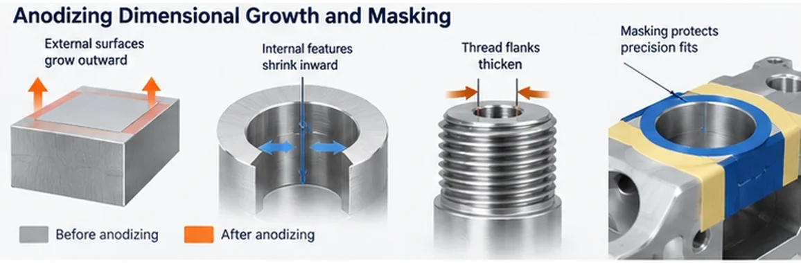
Dimensional Growth: Outer Diameter Up, Bore Diameter Down
The anodized film grows in both directions from the original machined surface: outward on external features and inward on internal ones. A commonly cited rule of thumb splits that growth roughly evenly between the two directions, but this is an approximation, not a fixed physical law.
The actual split depends on process parameters and should be confirmed with a trial part before it is locked into a tolerance budget. The practical consequence is straightforward: external dimensions grow slightly, bores and internal features shrink slightly, and any precision bore, bearing seat, or locating pin hole needs machined-in allowance to land within tolerance after the coating is applied.
Threads and Masking
The same dimensional growth affects thread flanks, which thicken as the coating builds up — enough, on a precision fit, to make an assembly noticeably tighter than it was before finishing.
Two responses are common: masking the threads or other precision surfaces to keep them free of coating, or machining a deliberate over-size allowance into the thread before anodizing so the finished thread lands in tolerance. Masking adds a process step and cost, which is a reasonable trade-off on features where the coating provides no functional benefit but a real assembly risk.
Cosmetic Zones and Edge Rules
Not every surface needs the same finishing standard. Distinguishing visible cosmetic surfaces from hidden or mating ones lets the finishing specification — and the acceptance criteria applied at inspection — focus effort where it is actually seen.
Edge break and chamfer requirements on visible edges affect both appearance and how evenly the anodized coating builds along that edge; the specific dimension should be called out on the drawing rather than left to shop-floor judgment.
GD&T and Tolerance Budgeting: Putting Numbers Where They Matter
For machined aluminum housings, precision has a cost, and that cost is not distributed evenly across a drawing. The most effective tolerance strategy spends a limited budget on the features that actually need it and leaves the rest of the part looser.
Functional vs. Non-Functional Tolerances
A drawing where every dimension carries a tight tolerance is not a more careful drawing — it is usually a more expensive one, with higher inspection time, higher scrap risk, and a higher unit price, on features where none of that precision does anything functionally useful.
The more effective approach is to identify which dimensions are actually load-bearing, sealing, or locating features, tighten those, and deliberately relax everything else.
GD&T for Enclosures: Position, Flatness, Concentricity
The GD&T symbols that recur most often on machined housings are position (for locating holes and pins), flatness (for sealing and thermal mounting faces), concentricity or coaxiality (for the rotating or optical interfaces discussed earlier), and profile (for controlling overall external form).
ASME Y14.5 and ISO 1101 remain the standard references for how these callouts should be applied and interpreted.
Tolerance Stack-Up and the Cost of Precision
A monolithic part accumulates less tolerance stack-up than an assembly of separately machined pieces, because there are fewer interfaces for error to pass through.
As a general trend, tightening a tolerance does not raise cost linearly — the relationship steepens as the tolerance band narrows, since it drives slower feed rates, more frequent in-process checks, and higher scrap rates all at once. Root-sum-square (RSS) tolerance analysis is a useful concept for understanding how individual tolerances combine across a stack, though the specific calculation depends on the stack being analyzed.
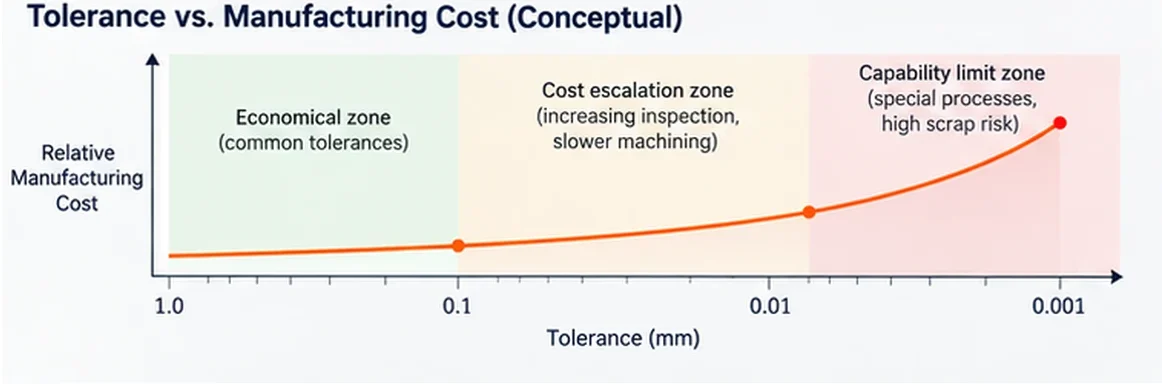
Where an achievable tolerance figure is quoted by a specific manufacturer as a capability claim, it should be understood as that supplier’s stated capability pending confirmation, and kept distinct from an economical tolerance band that a design would normally specify for cost reasons.
Designing for Inspection: Making the Part Measurable
For machined aluminum housings, a tolerance that cannot be measured economically does not actually control anything in production — it simply becomes a source of disagreement between the drawing and the part. Designing for inspection is the step that closes that gap.
CMM Access and Datum Alignment
A coordinate measuring machine probe needs physical clearance to reach the feature it is meant to verify. Features buried deep in a cavity, or bores too small for a standard probe tip, can be geometrically well-defined on the drawing and still be impractical to measure without custom fixturing.
The datum scheme chosen earlier has to be one that can actually be clamped and probed on real inspection equipment, not just one that is mathematically clean on paper.
Inspection Strategy and First Article
First article inspection — a full dimensional check of the first parts off a new setup — is typically more thorough than the sampling plan used for ongoing production batches.
Reserving CMM measurement for the functionally critical dimensions identified earlier, and using conventional gauges for the rest, keeps inspection cost proportional to the risk each dimension actually carries.
Setup Count and Cost Drivers: Where Machining Money Goes
Cost optimization for machined aluminum housings depends on controlling setup count, material utilization, feature complexity, tolerance requirements, finishing operations, and inspection scope.
Every design decision covered so far eventually shows up on a quote. This section connects those decisions back to the cost drivers a buyer is actually paying for.
Setup Count as the Primary Cost Driver
Each time a part is removed from the machine and re-fixtured, it introduces fixturing time, a new source of locating error, and often a dedicated work-holding setup.
Reducing setup count is one of the highest-leverage cost levers available, and it comes directly from decisions made earlier in this guide: unifying the datum and fixturing face, clustering features that can be machined from the same orientation, and using multi-axis equipment to access more faces without a manual re-fixture.
The Cost Driver Stack, Ranked
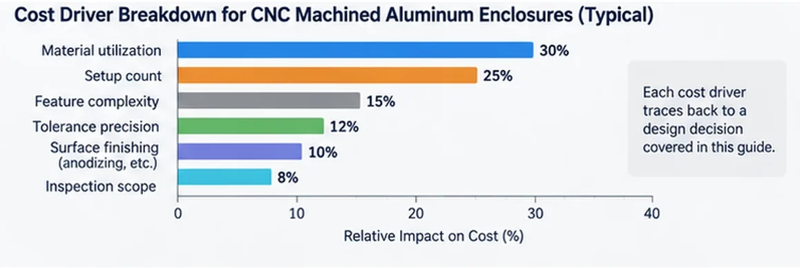
In rough order of typical influence: material utilization (how much of the stock ends up as the finished part versus chips), setup count, feature complexity (deep cavities, thread density, groove geometry), tolerance precision, finishing requirements, and inspection scope.
Each of these traces directly back to a design decision made earlier — the architecture choice affects setup count, the geometry choices affect feature complexity, and the tolerance strategy affects both precision cost and inspection scope.
Where Tolerance and Cost Intersect
Tightening a tolerance amplifies cost through several channels at once: slower feed rates to hold the dimension, more frequent in-process inspection, and a higher scrap rate on marginal parts.
For a buyer comparing quotes on the same drawing, a price difference is often explainable by which of these cost drivers a given supplier is weighting most heavily, rather than by one supplier simply being less efficient than another.
The Quote-Ready Package: What to Send for an Accurate RFQ
A design for machined aluminum housings can be technically sound and still generate a slow, inaccurate quote if the information a machinist actually needs is missing or scattered across multiple files. Assembling a complete package up front shortens the quoting cycle and reduces the chance of a quote based on assumptions rather than the actual design intent.
The Deliverables a Machinist Needs
A complete RFQ package typically includes a STEP or other neutral 3D model as the geometric authority and a 2D PDF drawing carrying dimensions, tolerances, and GD&T callouts.
It should also include the material specification and any required heat treatment; a clear flag on which dimensions are functionally critical versus nominal; an estimated annual volume and initial order quantity, since both affect process selection and pricing; and the finishing specification, including anodize type and any masking zones identified earlier.
The Quote-Ready Checklist
- 3D model in a neutral format (STEP preferred) matching the 2D drawing exactly
- 2D drawing with GD&T, critical dimensions flagged, and general tolerance class stated
- Material and temper specified, with any required certification noted
- Anodize type (Type II or Type III) and masking zones identified, if applicable
- Sealing requirements called out, including IP target and O-ring specification if used
- Estimated annual volume and initial order quantity
- Any features requiring special inspection (CMM, gauge, or first-article sign-off) flagged
Each line in this checklist maps back to a decision covered earlier in this guide — the architecture, the material, the geometry, the datums, the finishing, and the tolerance strategy all converge here, in the package that actually goes out for a quote.
A machining partner reviewing this package before quoting should be able to flag any missing item quickly, which is generally a faster path to an accurate quote than resolving open questions after the RFQ has already been submitted.