



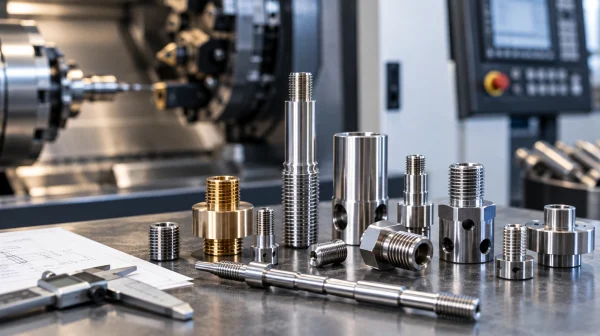
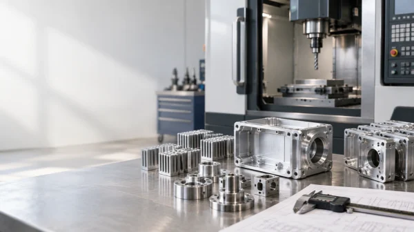
CNC screw machining is a practical production method for small-diameter, threaded, and cylindrical precision parts where cycle time, dimensional consistency, and material utilization directly affect manufacturing cost. The process can involve Swiss-type lathes, multi-spindle automatics, or conventional CNC turning centers, depending on part geometry, tolerance, material, and production quantity.
For engineers and buyers, choosing the right process is less about selecting a machine by name and more about understanding how the part will be supported, how threads and secondary features will be produced, and where tighter tolerances actually matter. This guide explains the main CNC screw machining methods, materials, thread-production options, standards, finishing processes, DFM considerations, and cost drivers that influence a successful production program.
What Is CNC Screw Machining?
Definition and Core Principles
CNC screw machining is a specialized form of precision turning used primarily for small or slender components produced from bar stock. Although the term originated with automatic screw machines developed for high-volume threaded components, modern screw machining covers many precision-turned parts whether or not the finished component actually includes a thread.
The category generally includes three machine architectures: Swiss-type sliding-headstock lathes, multi-spindle automatics, and conventional CNC turning centers configured for bar-fed production. Their common objective is efficient, repeatable production of cylindrical components while minimizing handling, setup changes, and unnecessary secondary machining.
Figure 1: A typical production flow for CNC screw-machined components, from bar-stock preparation through final inspection and shipment.
CNC Screw Machining vs. General CNC Turning
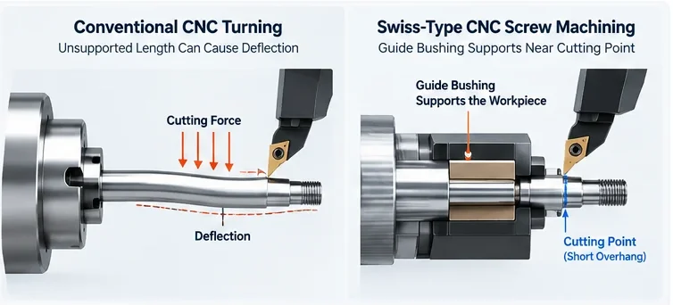
The most important mechanical difference is how the workpiece is supported during cutting. Conventional CNC turning normally grips the workpiece in a chuck or collet. As the unsupported length increases, cutting forces can produce deflection, vibration, or chatter, particularly on slender components.
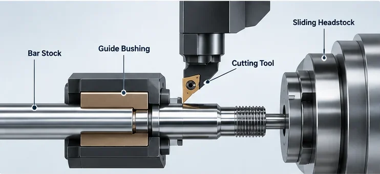
Swiss-type machines address this challenge by feeding bar stock through a guide bushing positioned close to the cutting tool. Supporting the workpiece near the cutting zone helps control deflection and makes the process useful for long, slender, small-diameter parts.
Conventional CNC turning services, however, remain highly flexible for prototypes, larger-diameter parts, shorter components, and lower-volume production. In practice, selecting between conventional turning and CNC screw machining depends on the complete combination of geometry, quantity, setup requirements, tooling, and tolerance.
When Is CNC Screw Machining a Good Choice?
A part may be a strong candidate for CNC screw machining when several of the following characteristics occur together:
- Small or moderate diameter parts produced efficiently from bar stock.
- Slender geometry where workpiece support is important for straightness and surface quality.
- Critical cylindrical features requiring controlled concentricity, roundness, or diameter.
- Repeat production where bar feeding and automation can reduce handling and cycle time.
- Multiple turned and milled features that can potentially be completed in one machine setup.
These are guidelines rather than fixed limits. Parts close to the boundary between two processes are often best evaluated by comparing actual setup requirements, cycle time, tooling, and total production cost.
CNC Screw Machining Equipment and Process Options
Swiss-Type CNC Lathes
Swiss-type lathes use a sliding headstock and guide-bushing arrangement that supports bar stock close to the cutting zone. This machine architecture is particularly effective for slender components where unsupported workpiece length would otherwise make conventional turning difficult.
Modern Swiss-type machines can combine turning, drilling, cross-drilling, milling, threading, and back-working operations within one automated production cycle. The ability to complete several features without transferring the part between machines can reduce handling and improve feature-to-feature consistency.
Swiss machining performance depends heavily on bar straightness, diameter consistency, surface condition, guide-bushing setup, tooling, and thermal stability. Demanding applications may require tightly controlled or centerless-ground stock.
Tolerance capability should never be assumed from the machine type alone. Material, part length, feature size, bar quality, tool condition, cutting parameters, thermal stability, and inspection strategy all influence the final result.
Multi-Spindle Screw Machines
Multi-spindle machines use several spindles to process multiple workpieces through a sequence of operations at the same time. Their main advantage is throughput, which can make them attractive for repeat production of suitable turned components.
The economics of multi-spindle machining depend on annual volume, component geometry, tooling, changeover requirements, and the ability to keep the machine running efficiently over longer production campaigns.
Conventional CNC Turning Centers
Conventional CNC turning centers remain an important part of screw-component manufacturing because they offer high flexibility. They are well suited to prototypes, first-article production, larger components, lower-volume programs, and designs where dedicated bar-fed processes do not provide a clear economic advantage.
For many projects, the most practical manufacturing strategy is determined only after comparing the same component on more than one machine platform.
Machine Selection Framework
| Factor | Swiss-Type | Multi-Spindle | Conventional CNC |
|---|---|---|---|
| Typical Geometry | Small, slender, feature-rich parts | Repeatable turned components | Broad geometry and diameter range |
| Workpiece Support | Strong support close to cutting zone | Process-dependent | Chuck / collet / tailstock based |
| Production Volume | Medium to high | High to very high | Prototype to medium volume |
| Feature Complexity | High with suitable live tooling | Moderate to high | High flexibility |
| Main Advantage | Slender-part control and operation consolidation | Throughput | Flexibility |
The most economical choice depends on the component rather than a fixed quantity threshold. Setup time, tooling investment, bar utilization, cycle time, inspection, and secondary operations should all be included in the comparison.
Thread Manufacturing Methods in CNC Screw Machining
Single-Point Thread Cutting
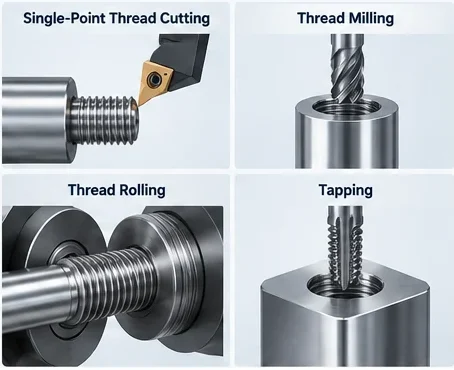
Single-point threading uses a cutting insert that follows the thread path over multiple passes until the required profile and depth are produced. It is highly flexible because thread pitch, diameter, and geometry can be changed through programming and tooling.
This flexibility makes single-point threading useful for prototypes, custom profiles, lower-volume programs, and applications where dedicated forming tooling cannot be justified.
Thread Milling
Thread milling uses a rotating cutter moving along a helical toolpath. Depending on cutter design, one tool may be able to produce several thread diameters that share the same pitch.
The process can be useful for difficult materials, larger threads, interrupted features, and applications where chip evacuation or tooling flexibility is especially important.
Thread Rolling and Forming
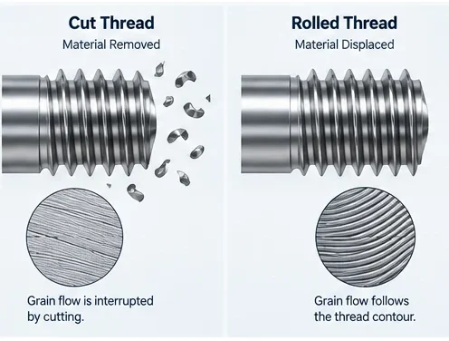
Thread rolling forms an external thread through plastic deformation rather than cutting away material. Because the material is displaced instead of removed, the grain flow follows the formed thread contour and compressive residual stresses can be introduced near the surface.
These characteristics can improve fatigue performance and surface quality in suitable materials. However, thread rolling requires appropriate material ductility, correct pre-roll dimensions, dedicated tooling, and sufficient production volume to justify the forming process.
Thread-forming capability depends on material condition, hardness, thread geometry, tooling, and forming load. Material suitability should be evaluated before specifying a rolling or form-tapping process.
Tapping and Thread Chasing
Tapping is one of the most common processes for producing internal threads. Cut taps remove material, while form taps displace material and therefore require a sufficiently ductile workpiece.
Thread chasing may also be used for external threading in suitable production environments. The best method depends on thread geometry, material, available machine capability, quantity, and functional requirements.
Comparing Thread Manufacturing Methods
| Method | Flexibility | Production Speed | Tooling Investment | Typical Use |
|---|---|---|---|---|
| Single-point cutting | Very High | Lower | Low | Custom threads, prototypes, varied production |
| Thread milling | High | Moderate | Moderate | Flexible production and difficult materials |
| Thread rolling | Lower | High | Higher | Repeat production and fatigue-sensitive parts |
| Tapping / forming | Moderate | High | Low–Moderate | Internal threads |
Materials for CNC Screw Machining
Material selection affects cutting speed, tool life, chip control, dimensional stability, corrosion resistance, mechanical performance, finishing options, and total part cost. For broader material guidance, see our CNC machining materials resources.
Free-Machining Steels and Stainless Steels
Free-machining steels such as 12L14 are widely used where fast cutting, good chip control, and economical production are priorities. Their mechanical properties and corrosion resistance, however, limit them in some applications.
303 stainless steel provides improved machinability compared with many other austenitic stainless grades. 304 and 316/316L offer stronger corrosion resistance but normally require more deliberate chip-breaking, tooling, and cutting strategies. 17-4 PH is commonly chosen where higher mechanical strength and corrosion resistance must be combined.
Aluminum, Brass, and Copper Alloys
6061-T6 aluminum is a widely used general-purpose alloy that machines efficiently and accepts several surface treatments. 7075-T6 provides substantially higher strength where structural performance is more important.
C360 brass, covered by ASTM B16, is known for excellent machinability and is often selected for high-speed turned-component production. Copper alloys may be chosen where electrical or thermal conductivity is a primary functional requirement.
Titanium and High-Performance Alloys
Titanium alloys such as Ti-6Al-4V are commonly used in aerospace, medical, and high-performance mechanical applications. Nickel-based alloys such as Inconel 718 serve demanding temperature, strength, and corrosion environments.
Compared with free-machining materials, these alloys typically require more conservative cutting conditions, appropriate tooling, stable coolant delivery, and careful heat management.
Engineering Plastics
Engineering plastics such as PEEK, nylon, and acetal are also used for precision threaded components. Their lower thermal conductivity and different mechanical behavior require sharp tooling and controlled cutting conditions to reduce heat-related distortion or poor surface quality.
Material Selection Matrix
| Material | Machinability | Relative Strength | Corrosion Resistance | Relative Cost | Typical Application |
|---|---|---|---|---|---|
| 12L14 Steel | Excellent | Moderate | Low | Low | General turned components |
| 303 Stainless | Good | Moderate | Good | Moderate | Corrosion-resistant precision parts |
| 316L Stainless | Moderate | Moderate | Excellent | Moderate–High | Marine, medical, and food-contact parts |
| 17-4 PH Stainless | Moderate | High | Good | High | High-strength precision components |
| 6061-T6 Aluminum | Very Good | Low–Moderate | Moderate | Low–Moderate | General structural parts |
| C360 Brass | Excellent | Low–Moderate | Moderate | Moderate | High-speed turned components |
| Ti-6Al-4V | Difficult | High | Excellent | Very High | Medical and aerospace applications |
| PEEK | Moderate | Application-Dependent | Excellent Chemical Resistance | Very High | Medical and chemical-exposure parts |
These comparisons are relative rather than absolute. Actual cycle time, tool life, tolerance capability, and surface quality depend on the specific part and process.
CNC Screw Machining Tolerances, Standards, and Inspection
Thread Tolerance Standards
Metric threads are commonly specified according to ISO 965-1, which defines tolerance grades and positions for internal and external metric threads.
Unified inch threads such as UNC, UNF, and UNEF are commonly specified using ASME B1.1. The required thread class should be specified directly on the engineering drawing, particularly where fit, interchangeability, plating allowance, or preload is important.
Dimensional Tolerances
ISO 4759-1 covers dimensional tolerances for bolts, screws, studs, and nuts. For custom machined parts, however, achievable tolerances depend on geometry, material, tooling, workpiece support, thermal stability, machine condition, and inspection method.
One advantage of Swiss-type CNC screw machining is the ability to support slender workpieces close to the cutting zone. This can help control straightness, roundness, concentricity, and surface finish where unsupported conventional turning becomes more difficult.
Mechanical Property Standards
ISO 898-1 covers mechanical and physical properties for carbon and alloy steel fasteners. ASTM F593 applies to several stainless-steel fastener products, while SAE J429 is widely referenced for mechanical requirements of inch-series steel fasteners.
The appropriate standard should be selected according to material, geometry, application, heat treatment, and customer requirements rather than relying only on a nominal material name.
Inspection Methods
Different inspection methods are appropriate for different features. Coordinate measuring machines can verify geometric relationships and dimensional features during first-article inspection or process studies. Optical comparators and vision systems are useful for profiles and small features, while GO/NO-GO gauges provide efficient thread verification in production.
Profilometers may be used when surface roughness requirements are specified, and statistical process control can help monitor dimensional stability across repeat production.
Production monitoring and process stability
3D dimensional and geometric verification
Non-contact profile and feature inspection
Surface roughness verification
Rapid production thread inspection
Figure 6: Common inspection methods used at different stages of precision screw-component manufacturing.
Surface Finishing and Secondary Operations
Secondary operations help convert a machined component into a finished part that meets corrosion, wear, appearance, cleanliness, and assembly requirements. See our surface finishing services for additional process information.
Passivation and Electropolishing
Passivation, commonly specified through standards such as ASTM A967, removes free-iron contamination from stainless-steel surfaces and supports formation of a corrosion-resistant passive layer.
Electropolishing removes a controlled amount of material electrochemically and can improve cleanliness, reduce micro-burrs, and lower surface roughness where required.
Plating: Zinc, Nickel, and Chrome
Zinc plating is commonly used as economical corrosion protection for carbon-steel components. Nickel coatings may be applied through electrolytic or electroless processes, while chrome coatings can be selected for decorative or wear-related requirements.
Because coatings add or remove material at the surface, thread dimensions and required final fit should be considered before machining dimensions are finalized.
For coated threaded parts, define the final thread fit first and coordinate machining allowance with the coating specification rather than treating plating as an afterthought.
Anodizing and Black Oxide
Anodizing is commonly applied to aluminum alloys for corrosion protection, wear resistance, and appearance. Different anodizing processes provide different coating characteristics and should be selected according to the functional requirement.
Black oxide is used on ferrous components where a dark surface and minimal dimensional change are desired. Its corrosion performance depends strongly on the post-treatment and service environment.
Deburring, Cleaning, and Packaging
Deburring methods may include vibratory finishing, centrifugal finishing, brushing, manual deburring, or specialized processes depending on geometry and edge requirements.
Cleaning and packaging requirements should reflect the final application. Precision parts may need protection from contamination, corrosion, impact damage, or mixing during transportation and downstream assembly.
Passivation
Stainless Steel
ASTM A967
Chemical treatment for removing free iron contamination and improving corrosion resistance.
Electropolishing
Stainless Steel
Surface Refinement
Electrochemical surface removal for improved cleanliness, smoothness, and micro-burr reduction.
Zinc Plating
Carbon & Alloy Steel
Corrosion Protection
Economical protective coating commonly used on steel components and fasteners.
Anodizing
Aluminum Alloys
Type II / Type III
Oxide coating used for corrosion resistance, wear performance, or cosmetic appearance.
DFM and Cost Optimization for CNC Screw Machining
Design decisions have a major effect on cycle time, tooling, inspection, and manufacturing cost. For more engineering guidance, see our DFM resources for precision machining.
Geometry Guidelines
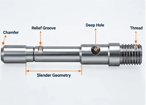
Length-to-diameter ratio, workpiece rigidity, thread runout, tool clearance, hole depth, feature sequence, and access for cutting tools are among the most important DFM considerations for screw-machined components.
Slender geometry increases sensitivity to material straightness and workpiece support. Relief grooves require sufficient room for tool runout. Deep holes may require different drilling strategies as depth increases, while unnecessary tool changes or secondary setups directly increase production time.
Deep-hole feasibility depends on hole diameter, depth, straightness, material, surface-finish requirements, available tooling, and coolant delivery. Review demanding hole features early in the DFM process.
Tolerance Strategy
Not every dimension needs the same tolerance. Applying unnecessarily tight limits to non-functional dimensions increases machining and inspection cost without improving product performance.
A better approach identifies the features that directly affect fit or function — such as mating diameters, threads, sealing surfaces, bearing locations, and datum relationships — and applies tighter controls only where necessary.
Batch Size Economics
Production quantity affects process economics, but there is no universal quantity at which one manufacturing method automatically becomes the best option.
For CNC screw machining, the real crossover depends on geometry, setup time, tooling, material, inspection, cycle time, secondary operations, and the supplier’s available equipment.
Flexible CNC Turning
Swiss CNC / Automated Turning
Swiss CNC / Multi-Spindle
Evaluate Forming + Machining Options
Figure 8: Illustrative process selection by production scale. Actual crossover points depend on the component, material, quality requirements, and manufacturing route.
Major Cost Drivers
The final price of a screw-machined component is usually influenced by several interacting factors rather than one single cost item.
- Material & Bar Utilization — alloy price, stock condition, diameter, and usable material yield.
- Setup & Changeover — programming, tooling, bar setup, and process qualification.
- Cycle Time — machining operations, simultaneous cutting, and tool-path efficiency.
- Secondary Operations — heat treatment, finishing, cleaning, deburring, and additional machining.
- Inspection Requirements — tolerance level, sampling strategy, traceability, and reporting.
Figure 9: Major cost drivers in precision screw machining. Their relative importance varies by design, material, production quantity, and quality requirements.
RFQ Preparation Checklist
A complete RFQ helps suppliers evaluate the part accurately and reduces unnecessary quoting assumptions. Whenever possible, provide:
- 2D drawing and/or 3D model.
- Material grade and any certification requirements.
- Critical dimensions and tolerances.
- Thread standard and tolerance class.
- Surface finishing or coating requirements.
- Estimated annual volume and initial order quantity.
- Inspection, traceability, and acceptance requirements.
Choosing the Right CNC Screw Machining Approach
Successful CNC screw machining begins with matching the component to the right combination of machine platform, material, thread-production method, tolerance strategy, secondary operations, and production quantity.
For some parts, Swiss-type machining provides the best support and operation consolidation. Other components are more economical on conventional CNC turning centers or multi-spindle equipment. The most practical answer comes from evaluating the actual design rather than applying a generic process rule.
If you are sourcing a precision threaded or cylindrical component, provide your drawing, material, quantity, surface requirements, and critical tolerances. A manufacturing review can then identify an appropriate process route and highlight opportunities to simplify production before quotation.
Send us your drawing, material, quantity, and technical requirements. We can review manufacturability, process options, tolerances, and production considerations before quotation.